PST-MLC fabrication
In this study, we worked on MLCs made of PST. These devices consist of a succession of Pt electrodes and PST in such a way as to obtain several capacitors all connected in parallel. PST has been chosen because it is an excellent EC material and therefore a potentially excellent NLP material. It exhibits a sharp ferroelectric–paraelectric first-order phase transition around 20 °C, which infers that its entropy varies similarly to what is represented in Fig. 1. Similar MLCs have already been described thoroughly for the purpose of EC devices13,14. In this study, we used 10.4 × 7.2 × 1 mm³ and 10.4 × 7.2 × 0.5 mm³ MLCs. The 1-mm- and 0.5-mm-thick MLCs are made of 19 and 9 inner layers, respectively, of 38.6-µm-thick PST. In both cases, the PST inner layers are intercalated between 2.05-µm-thick Pt electrodes. The design of these MLCs infers that 55% of PST is active, corresponding to the part in between the electrodes (Supplementary Note 1). The active electrode area is 48.7 mm2 (Supplementary Table 5). MLCs of PST were prepared by solid-state reaction and tape casting methods. Details of the preparation processes were reported in a previous paper14. One of the differences of the PST MLCs from this previous paper14 is the B-site ordering, which strongly influences EC performance in PST. B-site ordering of PST MLCs is 0.75 (Supplementary Note 2), obtained by sintering at 1,400 °C followed by a long annealing period of several hundreds of hours at 1,000 °C. More details of the PST MLCs are given in Supplementary Notes 1–3 and Supplementary Table 5.
Experimental set-up of the Olsen cycles
The main concept of this study is based on Olsen cycles (Fig. 1). For such cycles, we need a cold and a hot heat reservoir and a power supply able to control and monitor the voltage and current in the different MLC modules. Two different configurations have been used for these direct cycles, namely (1) a Linkam module heating and cooling one single MLC associated with a Keithley 2410 energy supply and (2) three prototypes (HARV1, HARV2 and HARV3) based on several PST MLCs connected in parallel with the same energy supply. In the latter case, a dielectric fluid (silicone oil of viscosity 5 cP at 25 °C, purchased from Sigma Aldrich) was used to exchange heat between the two reservoirs (hot and cold) and the MLCs. The hot reservoir consisted of a glass vessel that contained the dielectric fluid and was placed on top of a hot plate. The cold reservoir consisted of a thermal bath of the fluid tube containing the dielectric fluid in a large plastic vessel filled with water and ice. Two three-way pinch valves (purchased from Bio-Chem Fluidics) were placed at each end of the harvester to properly switch the fluid flow from one reservoir to the other one (Fig. 2a). To ensure thermal equilibrium between the PST-MLC stack and the heat transfer fluid, the period of the cycle was extended until the inlet and outlet thermocouples (placed as closely to the PST-MLC stack as possible) read the same temperature. A Python script governed and synchronized all of the instrumentation (sourcemeter, pump, valves and thermocouples) so that proper Olsen cycles were run, that is, the hot fluid loop started circulating through the PST stack after the sourcemeter had charged them so that they were heated up at the desired applied voltage of a given Olsen cycle.
Alternatively, we confirmed these direct measurements of harvested energy with an indirect method. These indirect methods are based on electric displacement field (D)– electric field (E) loops collected at different temperatures and enabling an accurate estimation of how much energy can be harvested by calculating the area in between the two DE loops, as depicted in Fig. 1b. These DE loops were also collected with the Keithley sourcemeter.
Harvester description
HARV1
Twenty-eight 1-mm-thick PST MLCs were assembled in a 4 row × 7 column parallel plate structure following the design described in ref. 14. The fluid slit in between the PST-MLC rows was 0.75 mm. This was achieved by adding double-sided-tape stripes acting as fluid spacers at the edges of the PST MLCs. The PST MLCs were electrically connected in parallel with silver epoxy bridges that contacted the electrode terminals. After that, a wire was glued with silver epoxy to each side of the electrode terminal so that it could be connected to the power supply. Finally, the entire structure was inserted into a polyolefin hose. The latter was glued to the fluid tubes to ensure proper sealing. At the end, 0.25-mm-thick type K thermocouples were embedded at each end of the PST-MLC structure to monitor the temperature of the inlet and outlet of the fluid. To do so, the hose had to be first perforated. Once the thermocouple was embedded, the same glue as before was applied in between the hose and the thermocouple wire to restore the seal.
HARV2
Eight individual prototypes were built, four of them with 40 0.5-mm-thick PST MLCs each, distributed in 5 column × 8 row parallel plate structures, and the other four with 15 1-mm-thick PST MLCs each, distributed in 3 column × 5 row parallel plate structures. The total number of PST MLCs used was 220 (160 0.5-mm-thick and 60 1-mm-thick PST MLCs). We refer to these two subunits as HARV2_160 and HARV2_60. The fluid slit in HARV2_160 prototypes consisted of two stripes of 0.25-mm-thick double-sided tape and a 0.25-mm-thick wire in between them. For HARV2_60 prototypes, we repeated the same procedure but with 0.38-mm-thick wires instead. For the sake of symmetry, HARV2_160 and HARV2_60 had their own fluid circuit, pump, valve and cold side (Supplementary Note 8). The hot reservoir, a three-litre container (30 cm × 20 cm × 5 cm) on top of two hot plates with rotating magnets, was shared by the two HARV2 subunits. All eight individual prototypes were connected electrically in parallel. In the Olsen cycle that led to 11.2 J of harvested energy, subunits HARV2_160 and HARV2_60 were operated simultaneously.
HARV3
One single 0.5-mm-thick PST MLC was placed in a polyolefin hose, with double-sided tape stripes and wires at the sides to create spaces for the fluid to flow through. Because of its smaller size, the prototype was placed next to the valve that supplies fluid either from the hot fluid reservoir or the cold one, minimizing the cycle period.
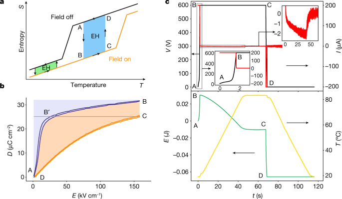
Olsen cycles
A constant electric field was imposed in the PST MLCs by applying a constant voltage throughout the heating leg. As a result, a negative pyroelectric current was generated and energy was harvested. After the PST MLCs were heated up, the field was removed (V = 0), and the energy stored in them was brought back to the sourcemeter, which corresponds to another contribution of the harvested energy. Finally, at the applied voltage V = 0, the PST MLCs were cooled down to their initial temperature so that a cycle could start again. In this step, no energy was harvested. We ran Olsen cycles with a Keithley 2410 sourcemeter by charging the PST MLCs at the voltage source and setting the current compliance to the appropriate value so that enough points in the charging step were gathered to enable a reliable calculation of the energy.
Stirling cycles
In Stirling cycles, PST MLCs were charged in voltage source mode at an initial electric field value (initial voltage Vi > 0), a desired compliance current so that the charging step takes around 1 s (and enough points are gathered for a reliable calculation of the energy) and cold temperature. Before the PST MLC was heated up, the electric circuit was opened by imposing current compliance I = 0 mA (the lowest value of current compliance that our sourcemeter could take was 10 nA). As a result, charges were kept in the PST MLCs and voltage increased while the sample was heated up. In the leg BC, no energy was harvested because I = 0 mA. After reaching the hot temperature and the voltage in the PST MLCs having been amplified (in some cases it was by more than 30 times, see Supplementary Fig. 7.2), the PST MLCs were discharged (V = 0), and the electrical energy stored in them was brought back to the sourcemeter at the same current compliance that they had been charged with initially. Because of the voltage amplification, the energy stored at the hot temperature was higher than the energy supplied at the beginning of the cycle. Thus, energy was harvested by converting heat into electrical energy.
Calculation of energy harvested and power
We monitored the voltage and current applied to the PST MLCs with a Keithley 2410 sourcemeter. The corresponding energy was calculated by integrating the product of voltage and current read by the Keithley sourcemeter over time, (E={int }_{0}^{tau }{I}_{{rm{meas}}}left(tright){V}_{{rm{meas}}}(t)), where τ is the period of the cycle. In our energy curves, positive values of energy mean energy we have to supply to the PST MLCs, and negative values mean energy we extract from them, hence harvested energy. The associated power of the given harvested cycle was deduced by dividing the harvested energy by the period of the entire cycle τ.